Tuesday, April 29, 2014

If 3 is good then 4 is better

The last post about KiCad (here) was based on the DistoMatic series of boards (eventually there'll be several). I'm trying standardize my connections to simplify the process and allow for greater use.

Previously my pinouts were this:
  1. 3v3
  2. 5v
  3. GPIO
  4. Analog
  5. GIO
  6. Ground
This works fine for the Ping))), MaxBotix, SharpIR, etc. sensors, as they only need voltage, ground, and 1 or 2 signal lines.

I came up with this pinout based on the MaxBotix so that one may be able to connect the sensors so that one can trigger the next one. The trigger-out from sensor #1 would go to the trigger-in to sensor #2.

But I was think that many devices use the SPI (wiki definition) protocol and it wouldn't work with my own spec. That needs Clock, Select, DataIn, DataOut pins, 1 more than what I have available. However, if I remove one of the power lines, then I would have 4 lines for data.

So going forward I'm going to only supply 5v to the my boards. If the sensor or breakout board needs only 3v3, then I can use a voltage divider or a regulator to bring down the voltage.

New pinout:
  1. 3v3
  2. GPIO
  3. GPIO
  4. Analog
  5. GIO
  6. Ground
I am trying to learn from those who came before me --
  • Gadgeteer has a 10 pin connector protocol, with 3v3, 5v and GND being standard places
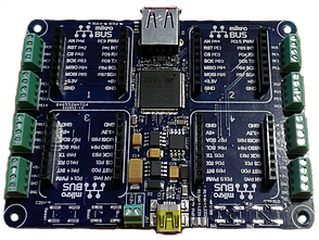
  • MikroElectronics has a connector with standardized pinouts for several protocols
  • Arduino has standardized pinouts on the connectors for the mCu breakouts.


Wednesday, April 16, 2014

Next project in queue - a mikroBUS.NET board

MikroElectronica produces a variety of hardware boards designed to ease the building of complex projects. To standardize the connections, they have come up with the mikroBus specification. Unlike the Arduino platforms, it specifies the type of function for each pin instead of simply breaking out all the pins from the MicroController.

The specification as found on the MikroElectronica site.

Various folks from the GHI forum and Oberon Microsystems  have undertaken building a .NET MicroFramework version of this system -  mikroBUS.NET. There are currently 2 mainboards under development: the Dalmatian with 2 mikroBUS sockets and the Quail with 4 sockets.


Dalamtian

Quail

Recently Bec a Fuel posted the progress of this endeavor in the form of a video demonstrating the brand new (and still underdevelopment) Quail board with various modules, NETMF framework and NETMF drivers running the Click boards.


To assist with the project, I'll be building a MBN (mikroBUS.NET) board and will be documenting the process for others to avoid my mistakes ;)


Friday, April 11, 2014

More KiCad learning curves - always double check!

The Good, the meh and the bad.

These boards are for the DistoMatic mainboards to inteface with Parallax Ping )))))) ultrasonic sensors.

tl;dr version:

Good news : Got my KiCad designed DistoMatic boards in the mail. 

Meh news : Throughhole pads are not on both top and bottom as they are in Eagle by default.


Bad news: Either the labels are wrong or my pins are in the wrong order in relation to the Ping )))))))).

The Meh

With Eagle, when you place a throughhole connector, it defaults to puttin the pin pads (where you apply 
solder to) to both top and bottom.  Below is the property for the 3 hole connector - notice there's no selection of which PCB layer put the pads on.


Contrast that property window with the one below, which is for the trace (the path for the current to go through on the board) which is set to be placed on the bottom layer.


Here's the corresponding property window for the "pinhead" in KiCad


Notice there's a layer selection in this window that wasn't there in Eagle. Since I was used to the style, I didn't even think to change the defaulted top layer section.

Even so I should have caught this when submitting the design to OSHPark.com. A great feature of their site is that when you upload a project, it will generate a preview of the various different layers.

Here's a previous version of the board (biggest difference being the SMT connector). You can see the gold pads on both the top (left) and bottom (right) layers.

Before ordering, and waiting 2 long weeks, I should have noticed that pads are only on the top (left) layer.

These are things that are taught by experience. Hopefully this helps others to avoid the same issue.


Monday, April 7, 2014

KiCad links (aka Hurry up and wait)

I've re-done my designs in KiCad and have been to submitted to OSHPark.com, now the waiting. Eagle is an established design software package, so many part libraries are already in place. In my initial dive into KiCad, I've had to layout some SMD pads so that's part of the waiting to ensure I got it right before going on to the next designs.

While I love the pricing and that you get only 3 boards (less wasteful than other services that have a minimum of 10), with OSHPark it takes about 2 (long!) weeks to get your boards back. So while I'm waiting here's a few helpful links.

***

First of all, here's the link to KiCAD official download page and site.

***

With Eagle, you just can submit the BRD file to OSHPark. However with KiCad, there's a list of different files you need to zip up and submit.

tymkrs (older version of KiCad) and Wayne and Layne (recent version) both have blog posts about the settings for submitting files to OSHPark.

****

To ensure that your design will work correctly with OSHPark (aka DRC), here is a link from an Electronics.StackExchange question that covers track width and other settings.

****

Here's a couple of videos and links that have helped me to learn KiCad, I would like to think, quickly:

Contextual Electronics is an online teaching company specializing on electronics. They have a 6 part tutorial series that walks you from concept to finished design for a 555 timer based blinky. Here's a link to the entire series in a single page.

Dave from EEVBlog has a first impression video where opens an existing design without any primer on the software and attempts to figure it out. It's both informative and very entertaining!

CAD Tutorials has some helpful videos as well